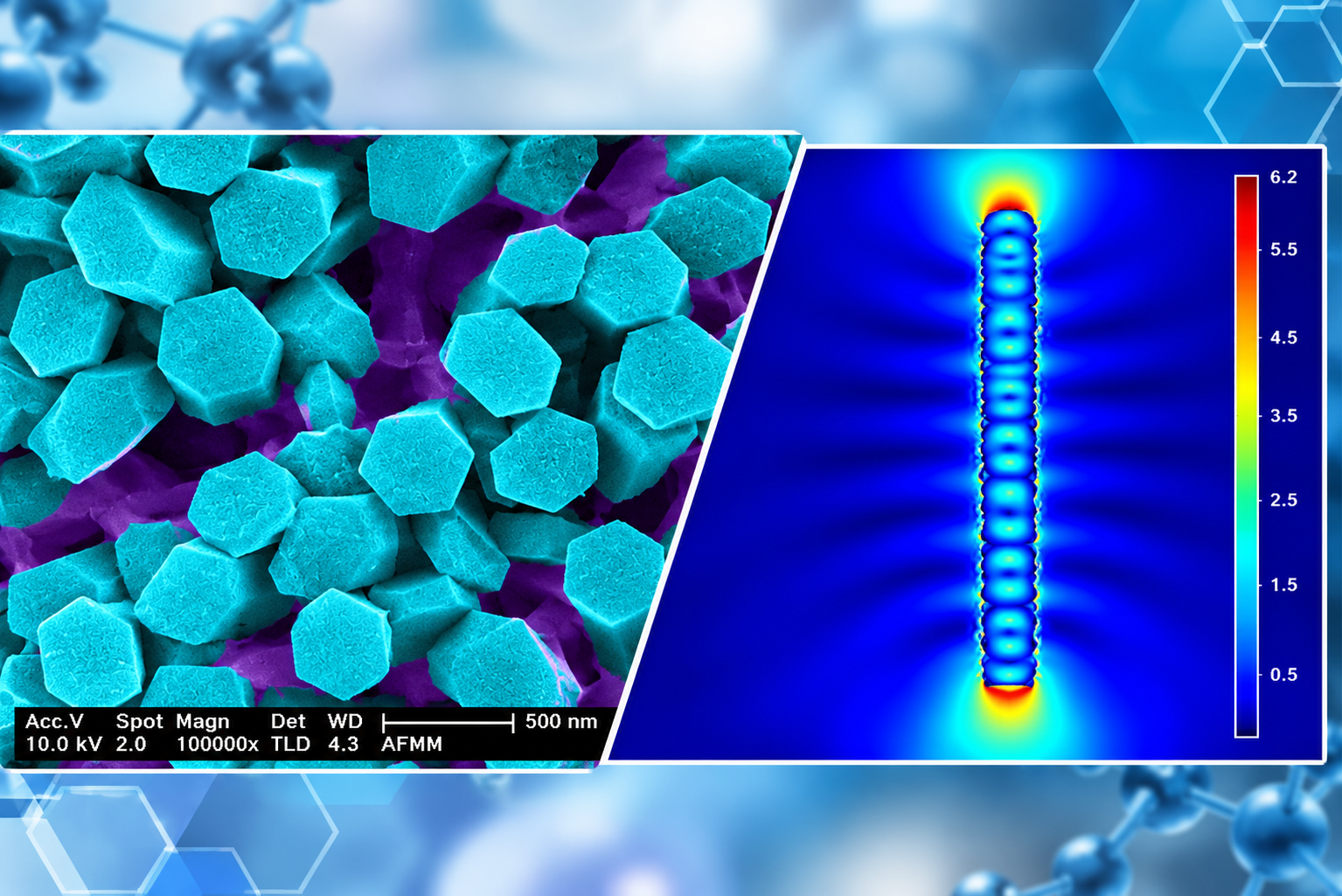
Study of Electro-mechanical Actuation in Designed Micro-interfaces
Load bearing capability of a multilayered structure demonstrated conjugative role of hybrid constituents including carbon nanotubes. The parametric evaluation of multi effects on actuation mechanism of designed materials is being explored. Mechanical motion of nanoscale objects has drawn tremendous interest in various fields like MEMS based devices for efficient ultrahigh actuation, tools for atomic manipulation, precise motion control in systems. Energy efficient tools etc. Our approach on developing opto-electronic actuators from carbon nanotubes has demonstrated vast variety of applications through the implementation of novel approaches to enhance actuation.
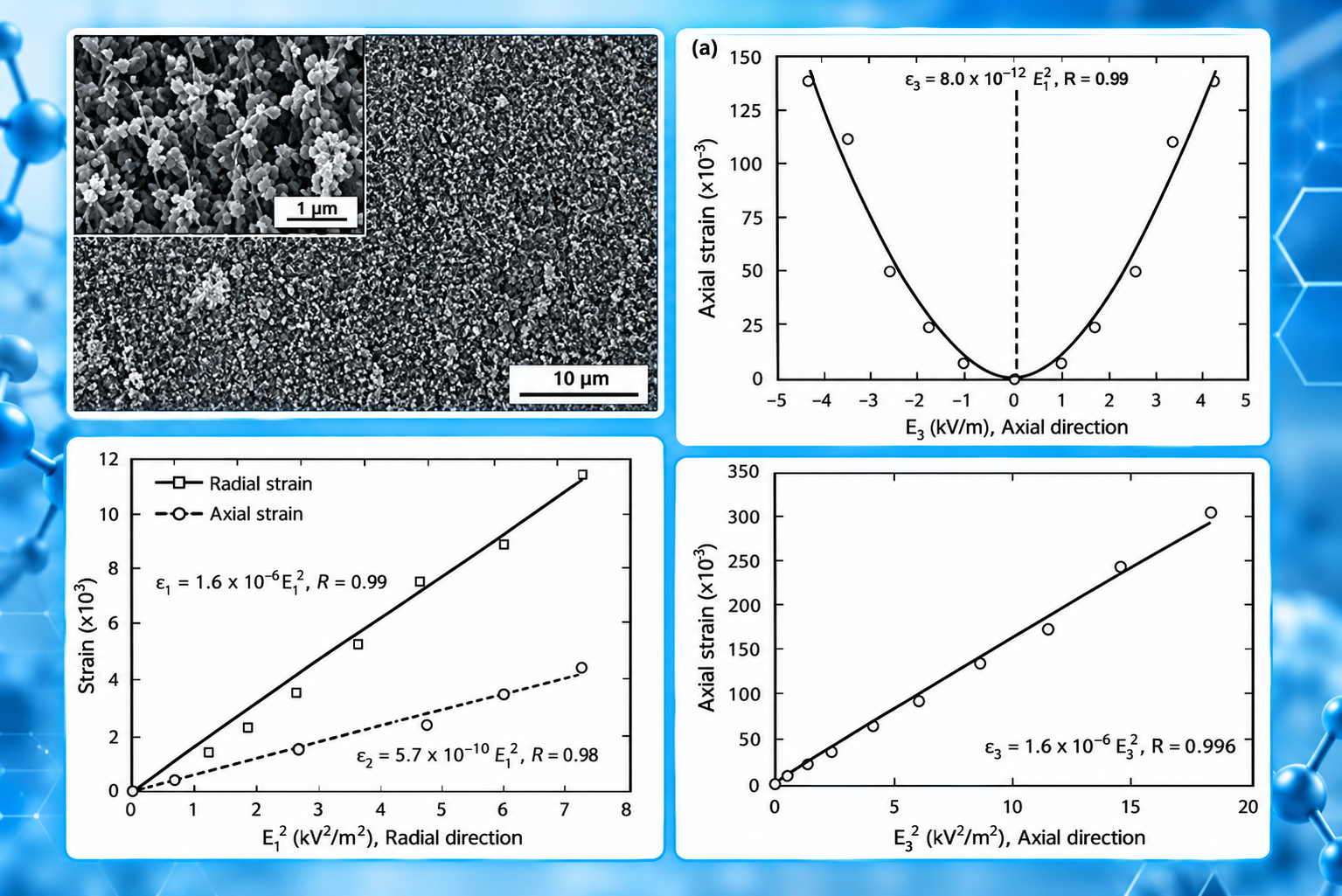
Electric field induced ultra-high actuation in a bulk carbon nanotube structure
Figure: CNT sample loaded with copper oxide nano-particles. Electric field induced ‘‘steady-state’’ actuation, in terms of (a) axial strain, in the CNT cellular structure as a function of the applied electric-field in the axial direction.
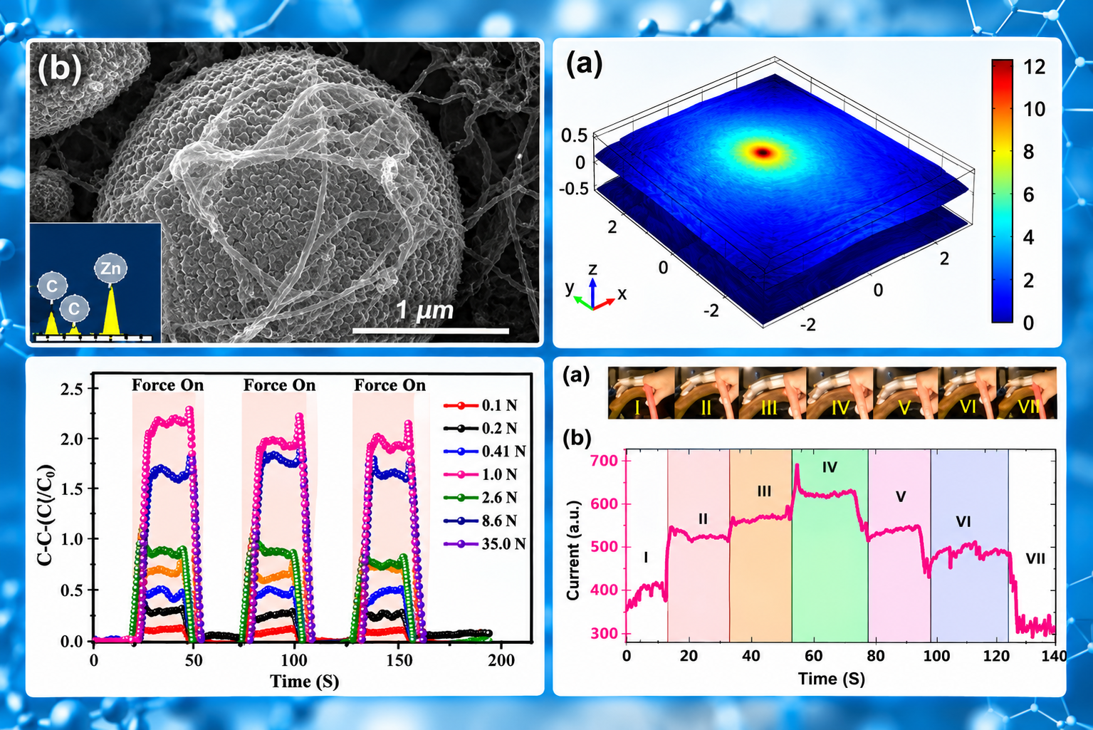
Capacitive behavior of carbon nanotube thin film induced by deformed ZnO microspheres
Figure: SEM image of the surface of a single ZnO microsphere. Simulation of hybrid ZnO single microsphere/MWCNT structure. Cyclic response of the device at different applied forces. Motion detection using the fabricated flexible device. (a) Photographs of the motion of the finger when it was gradually folded (I–IV) and released (V–VII). (b) The DC current response of the device.
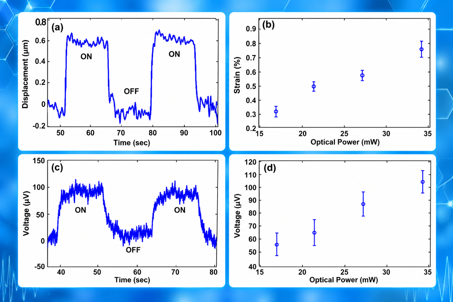
Coupling of photomechanical and electromechanical actuations in carbon Nanotubes
Figure: (a) The induced displacement in the MWCNT sheet plotted with the exposure time of the IR source. (b) The induced strain is plotted with IR laser power varying from 17 to 34 mW. (c) Generation of the photovoltage is shown with the IR exposure time. (d) Magnitude of photovoltage variation with the IR power.
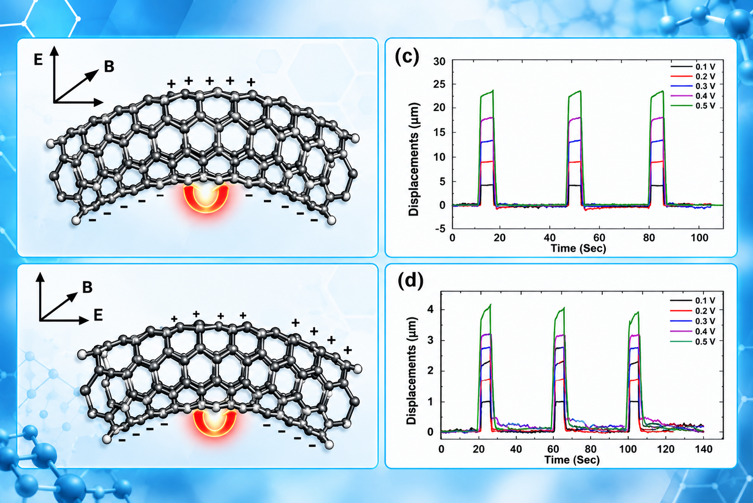
Giant actuation in bulk carbon nanotubes under coupled electric and magnetic fields
Figure: (a) Unequal separation of charges along the radial direction of the CNT leading to an enhanced actuation under the configuration of axial actuation. (b) Charge separation along the axial direction of the CNT under the configuration of radial actuation. Displacement plotted against time for (c) axial (d) radial actuations. Arrows indicate the direction of the induced torque.
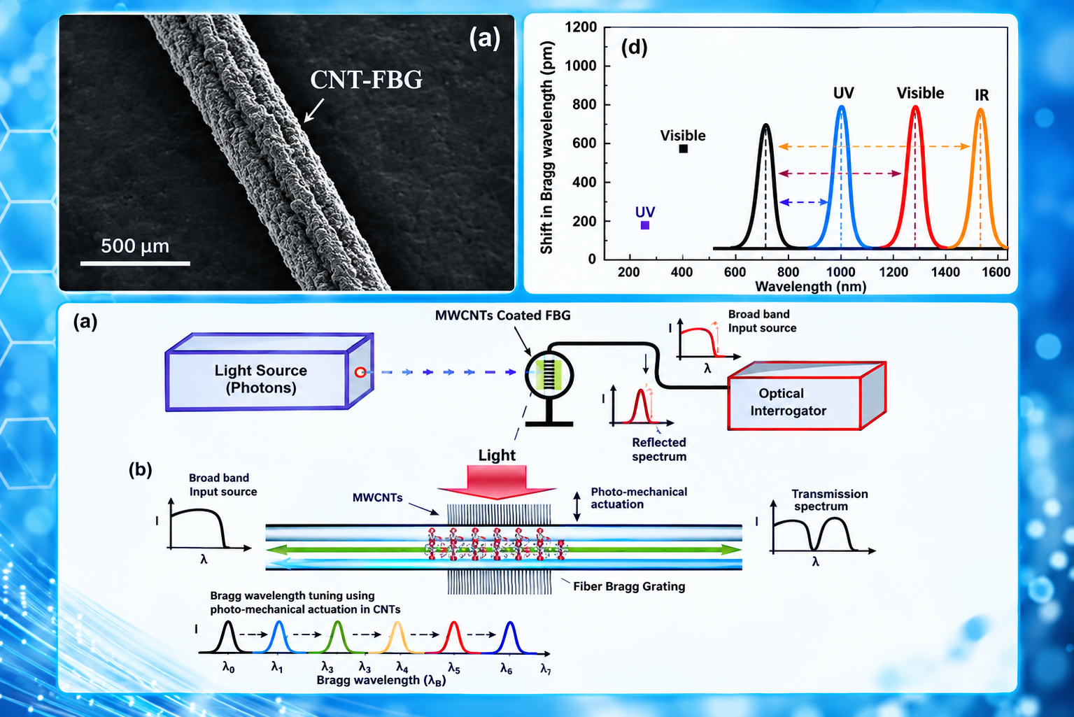
Carbon nanotube coated fiber Bragg grating for photomechanical optic modulator
Figure: SEM image of the CNT, coated around circular surface of the FBG. the comparison of the Bragg wavelength shift observed with respect to different wavelengths of light.
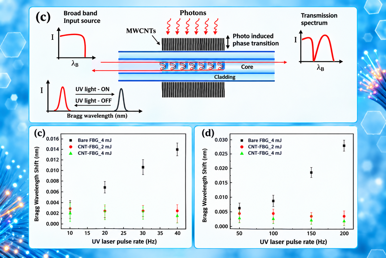
Monitoring of ultraviolet pulse rate dependent photomechanical actuation in carbon nanotubes using fiber Bragg gratings
Figure: Shift in the Bragg wavelength of CNT-FBG is plotted with time to show pulse rate dependence.
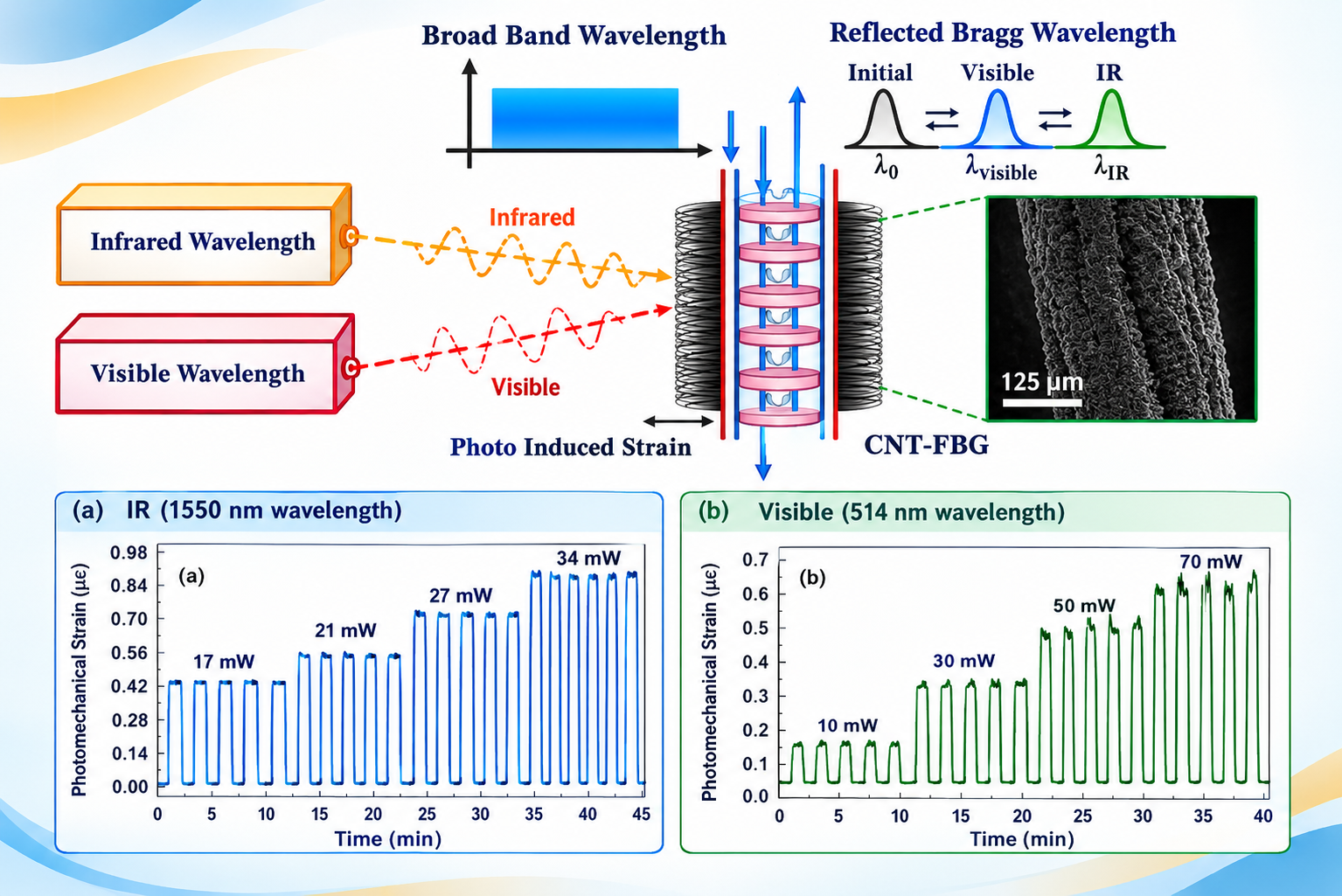
Effect of optical wavelength on photo induced strain sensitivity in carbon nanotubes using fiber Bragg grating
Figure: Schematic of the experimental setup used for controlling and monitoring photo induced strain in CNT upon exposure to infrared and visible wavelengths. Photo elastic characteristics of CNT-FBG system for five exposure cycles of IR and visible radiations; (a) Photo induced strain as a function of increase in the IR power (17–34 mW); (b) Photo induced strain as function of increase in visible power (10–70 mW).